mine has disconnected and jus wondering where the plug is located
cheers peoples
tacho wire location
Moderators: IMC, Club Staff
-
ms_fto

- Newbie

- Posts: 16
- jedwabna poszewka promocja
- Joined: Tue Nov 25, 2008 6:00 pm
-
vipfto
- Forum Moderator
- Posts: 4154
- Joined: Mon Oct 29, 2007 5:00 pm
- Location: Adelaide
have a look at below thread for ecu pinout diagram for revs
how do you know its loose as plugis behind dash cluster should be two serial style plugs
http://www.ftoaustralia.com/modules.php ... cu+diagram
how do you know its loose as plugis behind dash cluster should be two serial style plugs
http://www.ftoaustralia.com/modules.php ... cu+diagram
FTO GR-TURBO
172KW ATW @ 11PSI
172KW ATW @ 11PSI
-
dstocks

- National Vice President
- Posts: 9529
- Joined: Fri Jun 24, 2005 5:00 pm
- Location: Utopia
- Contact:
I think a bodgy ignition failure sensor will cause the tacho to stop functioning.....
Complete FTO (http://www.completefto.com.au/completefto.asp) 
If you are trying to contact me and not getting a quick answer, its because im disorganised. Hassle me and ill get back to you
If you are trying to contact me and not getting a quick answer, its because im disorganised. Hassle me and ill get back to you
-
Bennoz
- National President
- Posts: 23676
- Joined: Fri Jan 21, 2005 6:00 pm
- Location: Sydney
- Contact:
There's a couple of sensors that can cause it to go funny. The tacho wire usually doesnt just 'fall off'
I'd check the error codes to start with:
http://www.ftoaustralia.com/modules.php ... ic&t=14667
I'd check the error codes to start with:
http://www.ftoaustralia.com/modules.php ... ic&t=14667
-
Bennoz
- National President
- Posts: 23676
- Joined: Fri Jan 21, 2005 6:00 pm
- Location: Sydney
- Contact:
The error codes will tell you what sensor it is, but if thats in the too hard basket, start with the Ignition Failure Sensor
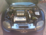
Looking from the front of the engine bay, just to the left of the air filter box, there is a tall 1" vertical metal pipe with a silver filler cap. Just behind this at the base is a small black box, about 1.5" square with a 4pin plug attached, bolted to the engine with 2 bolts (I think 10mm). This is the ignition failure sensor. Be careful removing the 4 pin plug, it has a securing wire which must be unclipped and pulled up before the plug can be removed.
How to check if IFS using a multimeter
1. Remove the dash cluster to reveal 2 multi-pin plugs. Start engine.
2. Looking at the left plug (C05) locate pin 18 (bottom row 5 in from left-white wire)
3. Set multimeter to read more than 5V. Put +ve probe to this pin and -ve probe to earth. (Use bolt in centre of console recess for convenience)
4. If multimeter does not read 5V then the problem is IFS or wire from IFS to dial console....stop engine..
5. Set multimeter to measure continuity. Remove IFS multiplug and locate white wire (2nd right as you look at it, best to strip back some of the cable covering to locate).
6. Put 1 probe into pin 2 of the connector (harness side) and the other to C05 pin18). You should hear a tone if the wiring is ok. If not then there is a break....(good luck in finding it...best to put a new wire in.)
If you wish you can check the continuity of wiring from the ecu to the IFS by probing ecu pin 51(white wire)...not pin 58 as book says...to pin 2 on IFS multiplug. Not really necessary unless you have a break.
If you don't have a multimeter......just change the IFS