ok so the wiring turned into a simple but time costly kind of a job. While the new engine harness was included here is what i had to achieve
*note* The FTO ecu plugs go into the firewall and then around the back of the fan motor and the ABS half goes straight down behind the carpet. they are impossible to get out without taking the dash out and loosening off the motor mounts from the firewall itself. I have no put them back behind the motor instead sending all plugs straight down the ABS loom path and back under the motor.
1. The GSR loom and the FTO looms had to be unbound and each have its ABS sub loom removed.
2. The FTO ABS loom was then combined with the GSR Engine Loom.
3. The pressure switch is on the opposite engine bay side in the GSR. 2 New wires were run for this.
4. There 3 interior plugs near the ECU for ABS, Dash, Speed Sensors had there heads removed (different plug type) and the 3 FTO ones soldered and shrink wrapped on.
This required both the FTO and Evo4 wiring diagrams (the CM5a diagram is not online, the evo 4 is the same just ignore the AYC section)
5. Using heads from the FTO loom I was able to make patch leads between the engine bay GSR plugs (to abs relay, fused link etc) to the FTO's plugs (A13 A14)(two plugs under the fuse box)
6. The alternator needed all 4 wires connected to one of the GSR's engine bar plugs (cant remember the plug code) stupidly the FTO diagram shows the pins in order 4 2 3 1 and the GSR 3 4 1 2 which caught me up when trying to match the two different colours for a solder.
7. The GSR also had a dedicated 60A fuse on the battery terminal for the ABS power source, where the FTO gets its from the 100A fused link. I converted it just in case its because the new ecu has a larger amp draw, but i doubt it.
8. Re wrap the entire loom and get it back into the firewall.
9. (Did this ages ago but for you guys) the reflash connector is hiding all tapped up under your dash above the ODB-II port. it has a grean wire that goes to one of the 3 plugs i reheaded near the ECU. HOWEVER the fto loom (ecu side) from those plugs is missing the pin for reflash. If you want to reflash your FTO ECU ROM or now in my case a EVO 6 ECU you need to wire this missing pin to pin 79 on the ECU (either ECU same pin no)
Spent 4 nights just doing this wiring. its not hard and if you read the diagrams you will work it out.
PROTIP: draw all three interior plugs on paper and label the pins. go through the diagrams for the fto and label (function and colour) every pin and in three plugs. Do the same for the GSR plugs. Once ALL plugs pins are accounted for and labeled, then cut the plugs and solder party. This will be fast and simple and much much easier then "ok green gsr > look in diagram > ok engine light > look in FTO diagram for engine light > ok pink > join" it will also ensure you dont miss any since all three plugs use wires from each other plug.
Started the engine. All dash is happy. check MUTIII logging, all sensors seen. Happy days.
Connected the EVO 6 ECU (changed the injector scaling and maf scaling to suite) engine starts all is also happy (remove for now till car is driving around without a issue.

the reflash connector for you guys.


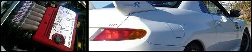
as it stands right now.