Here's a proposed DIY that recycles the now-defunct FTOWA web page on this subject.
It would benefit from a "merge" with the existing ECU code list posting on this forum. Consequently, I have cut out the error code list from the text.
Hope this is usable...
Rich
------------------------------------------------------------------------------------
The FTO's engine ECU monitors everything from sensors to injectors, solenoid valves to ignition. If it notices a problem, it records this in the form of a diagnostic code. A Mitsubishi dealer equipped with the right MUT-II diagnostic setup is apparently capable of accessing these codes.
But what if no such service is available to you? The FTO Workshop manuals do not provide any alternative method for extracting diagnostic codes.
Fortunately, the EVO Workshop manuals show a much easier way! Although the codes differ from the FTO, the method of extraction is identical... and the whole process requires nothing more than a single electrical lead...
Disclaimer: Do not attempt any wiring modifications yourself without (a) checking the connections, wire colours, etc. on your own vehicle, and (b) knowing what you are doing. I take no responsibility for any cooked wiring, ECUs or anything else you may feel like playing with. Any work done on your own vehicle is done so at your own risk...
The first step is to remove the panel underneath the steering wheel. This simply requires the removal of four screws. Note that the bonnet release cable and lever will still be connected to this panel - just drop the panel down and keep it out of the way.
Now if you crawl under there, you will notice an interface socket on the left hand side, about level with the bottom left screw you removed a moment ago.
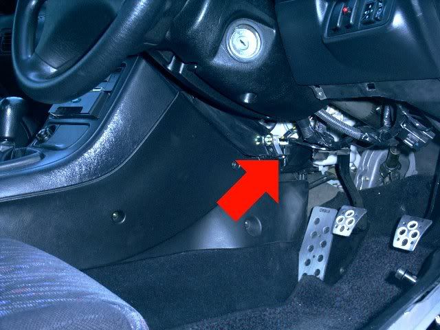
This is the location of the diagnosis connector, and I believe this is where a MUT-II unit is connected.
As I noted before, though, we don't need a MUT-II to do our dirty work! The EVO manual states...
Earth No. 1 terminal (diagnostic control terminal) of the diagnostic connector. Turn on the ignition switch.
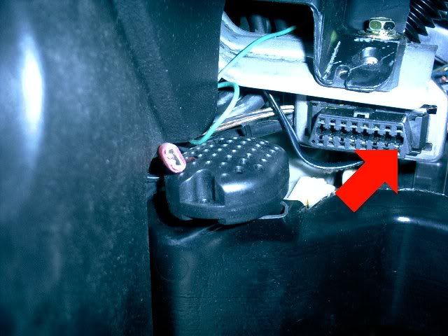
The image above was taken with the camera facing directly up. The "top" of the picture is oriented to the rear of the vehicle. Incidentally, the strange circular thing in the centre of the frame is simply the alarm's glass breakage sensor.
As noted before, we must earth No. 1 terminal on this connector. The pin in question is the bottom right one in the picture - highlighted.
All we have to do is ground out this pin by using a single cable. With the engine ignition switch on, the computer will flash the engine warning light to indicate any stored diagnostic code(s).
Because it was a bit of a pain getting in there and grounding this pin, I decided to find a less fiddly way of triggering an error code output...
At the back of the diagnostic plug, it was clear to see that the relevant pin was connected to an easily accessible lead (grey with red stripe on my 1995 GPX, but apparently a different colour on some other FTOs).
I used a standard patch connector to attach an extra wire to the relevant lead (see image below, highlighted).
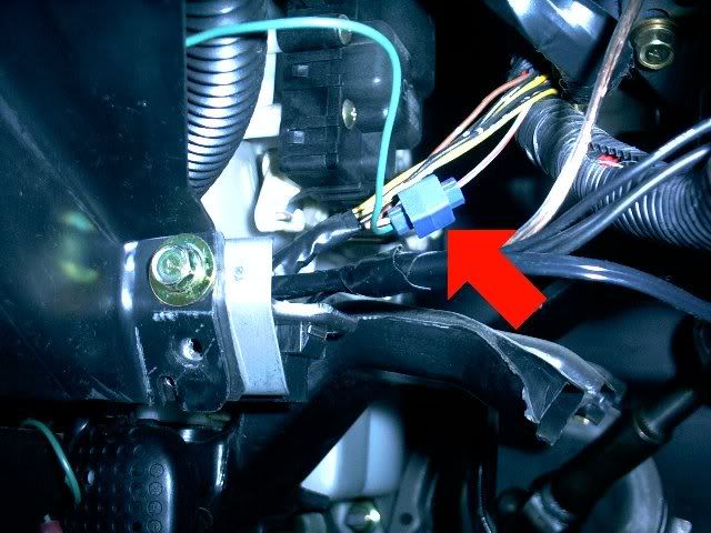
Now it is simply a matter of grounding out the permanent diagnostic lead stowed under the dash.
So what does an ECU diagnostic code look like when it is displayed?
Well, it looks a lot like this:
This is blinking out diagnostic code 31. It does so by blinking the engine warning light for 3 long flashes and 1 short flash.
If no codes are currently stored, it will simply flash continually, once per second.
I assume that if more than one code is stored, it will display each one in a repeating sequence, eg. 31, 52, 64, 31, 52, 64...
To clear the codes, simply disconnect the car battery for 20 seconds or so.
------------------------------------------------------------------------------------